Bathroom partition dimensions are critical when preparing to order materials for commercial restrooms. A little planning will make sure your installation process is smooth and flawless.
Commercial partitions will sometimes require a custom layout. Custom layouts are not anymore expensive, however, they are not as common as a standard 3' compartment.
Your layout dimensions need to be precise when having a company quote your restroom partitions. This is because most bathroom partitions cannot be cut in the field when installing. This would damage the partitions unless the material is solid plastic.
Common partition material is like a plastic cutting board you use in your house. Some materials use a honey comb cardboard on the inside for support with two sheets of steel on the outside. This would be very hard to cut and could cause issues to the partition.
Key Facts for Understanding Your Bathroom Partition Dimensions
A simple overhead layout is the best route for all toilet partition quotes.
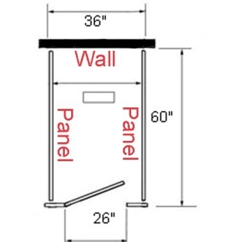
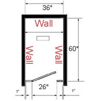
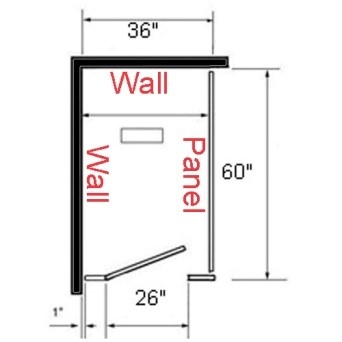
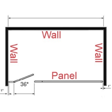
The layout should include where your tiled walls are, as well as, how wide and deep the compartments you want them to be.
Standard toilet stalls are 36" wide by 60" depth.
Partition stalls can have a minimum depth of 48" in most cases or up to 78" depth if needed.
You want to make sure you are measuring exactly where the partitions will be placed, because bathrooms are not always exactly square.
For ADA Handicap compliance compartments, all new construction must have out swing doors with no more than 4" from corner diagonally to the toilet with 18" center from the nearest wall or partition.
The minimum dimension is 60" wide on the inside by 59" deep also on the inside. This also would need to be a 36" door which a wheel chair could fit through.
Ambulatory accessible compartments are 36" wide at a minimum and also have a handicap door which is usually 32".
Options for Bracing Your Partitions
Overhead brace floor mounted partitions are the most common in the United States. This style is an easy installation with no ceiling or special flooring needed. The most economical solution for high traffic areas and overall height is 82".
Ceiling hung partitions are great for easy floor maintenance with a clean and contemporary appearance. Maximum ceiling height is 123.5" with most manufactures.
Floor mounted partitions are great for lower ceilings and lower traffic areas. The overall height is 70".
Floor to ceiling braced partitions are the best for high traffic areas such as airports and high schools. Extra support from floor to ceiling. Maximum ceiling height is 122" with most manufactures.
Over size panels and door for extra privacy are also available. Maximum height for a door is 71-1/2" and panels are 76". No sight options are also available which include continuous brackets and full length door stops and hinges.
Understanding the Material Options
Powder coated steel is the least inexpensive and used the most in the United States. There is a standard in the industry with most factories making this product the same way. This product is spray painted on top of steel with a honeycomb cardboard on the interior for support of the doors, panels and pilasters.
Plastic laminate is used in commercial businesses and churches with less traffic. The laminate usually comes from Formica or Wilsonart and is adhered to particle board on 6 sides. This is a high pressure process.
Solid plastic material is a high density poly ethylene that is made to last for 30 plus years and is very durable and moisture resistance. These days they are used in high schools, pool restrooms and more.
Stainless steel has a brilliant smooth surface type 304 with #4 brushed stainless steel finish. This product is great for easy maintenance and used in airports, high end restaurants and more.
Solid phenolic comes in black core and a color thru option. The black core uses a laminate for the two face sheets and the four edges are black. The color thru is similar to the solid plastic, but is a very smooth texture.
What You Need for Toilet Partition Quotes
Simple over head drawing.
Show where the walls are.
How wide and deep the compartments are.
Overall dimension for between walls.
Optional toilet bowl centers for better visual.
If not sure we can fill in the blanks.
Material type?
What style bracing? Most common Overhead braced.
We send all customers detailed drawings for approval.
All quotes include all necessary hardware and brackets to complete the job.
How to detail a wall plate: a sift through the guidance
Its less straightforward than you might think
A wall plate is a very common detail in small to medium-sized buildings in the UK. So common, in fact, that you might expect its design to be straightforward and for any associated guidance to be simple.
As with most things, reality is more complicated. You can find guidance in numerous technical documents but none of it is comprehensive and some of it is confusing. Surprisingly, some guidance advises doing things according to local practice rather than providing recommended solutions.
In this post I want to explain the issues involved in detailing a wall plate and its fixings and review the guidance* so that you can confidently develop details that comply. The scope of the post is limited to wall plates on masonry walls supporting timber roofs, although wall plates are used in other situations such as on sleeper walls supporting timber floor joists.
I also want to show you how an in depth look at a basic detail will help you begin to develop your expertise in building technology. I'll look at other common details in future, but for now, wall plates seem as good a place to start as any.
The post, which is a 15 min read, covers the following topics:
the purpose of a wall plate
what size should a wall plate be?
how should a wall plate be installed?
holding down and lateral restraint
is the wall plate structural?
my preferred solution
summary
Note *: In developing the post I've referred to relevant guidance, text books and trade literature, a summary of which can be found here together with a brief commentary.
The purpose of a wall plate
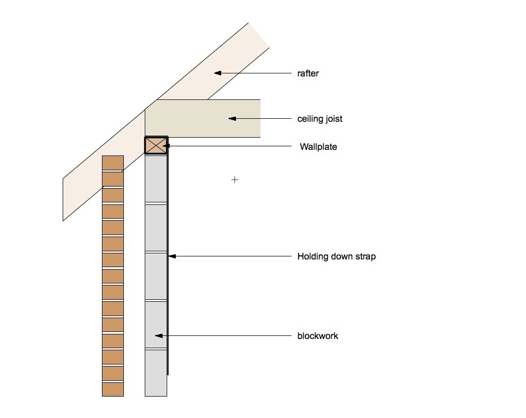
Timber wall plate on blockwork inner skin supporting a timber roof
The most common form of building construction in the UK comprises a timber pitched roof supported by masonry walls. A timber wall plate is installed at the top of the masonry wall and the roof structure is fixed to it.
During construction, the completion of the masonry wall doesn't just mean a change in structure from wall to roof, it also marks a change in trades, from bricklayers to joiners.
When the joiners start work, they want confidence that they're working to something that has been correctly 'lined and levelled' and that there is a simple and quick method for fixing the roof timbers.
In the majority of timber roof structures, all of the rafters and ceiling joists are the same and have their ends cut to identical profiles. In order for the joiners to work efficiently they work in 'production-line' mode, first cutting all of the roof timbers at ground level and then fixing them in position quickly, in a repetitious sequence.
Although taking the trouble to install the wall plate takes time, doing so has the advantage that the roof structure can be constructed accurately and efficiently.
Some guidance documents also refer to the wall plate as a means of distributing the loads from the roof in to the wall but this is mis-leading. While it is true that the roof loads have to pass through the wall plate, masonry has a higher compressive strength than softwood and hence the wall does not need the wall plate to spread the load; that's not what it's for.
Note: In timber-framed walls, the wall plate has to span between the vertical timber studs and therefore has more of a structural role in distributing the roof loads in to the wall.
Rafters cut to wall plate. Wall plate fixings and ceiling joists yet to be installed.
What size should a wall plate be?
When I started working, I was advised by someone (I don't remember who) that wall plates should be from softwood timber with a section size of 50x100mm. That is what I specified until, years later, a building inspector told me that the section size should be 75x100mm.
This is a good example of what often happens in building construction; we follow what we've been told without really understanding why. We're just grateful for advice from someone who speaks with authority.
But do we question that advice and do we bother to look at the technical guidance on the subject? We should, but often we don't.
Here's a summary of guidance on wall plate size:
The Building Regulations, through Approved Document A, doesn't give any advice on wall plates at all. This is an interesting fact and means that wall plates are not a specific requirement of the Building Regulations and are therefore, strictly speaking, outside the scope of a building inspector's remit.
However, they are a common solution and if you do intend to install a wall plate, Approved Document A also allows you, as an option, to refer to BS 8103-3 which includes the following note:
'In England & Wales it is normal for wall plates to have a basic thickness of 38mm, whilst in Scotland thicknesses of 25mm or 47mm are typical. These thicknesses are acceptable for this Part of BS 8103. '
Hence this British Standard doesn't suggest a width and, as far as depth is concerned, it only refers to what is done in practice. It does say, however, that the quoted thicknesses are acceptable, but does so without any explanation. Quite why a 25mm thick wall plate is acceptable in some parts of Scotland but not elsewhere remains a mystery.
NHBC Standards 2020 (which are applicable to the UK) is roughly similar in stating that wall plates should be '38x100mm or in accordance with local practice.'
Barry: Construction of Buildings Vol 1 states that 'it is usual for wall plates to be 75x100mm.'
Chudley & Greeno: Construction Technology has diagrams with wall plates labelled consistently as 50x100mm.
Armed with this variety of guidance, how do you reach a conclusion regarding the correct size of the wall plate?
Firstly, there obviously isn't a universally correct answer. In England & Wales, if you specified a 38x100mm wall plate, or thicker, you would appear to be complying with the British Standard and NHBC requirements.
So why would you specify anything thicker?
The wall plate has to be jointed and fixed to the wall (as described below) and having a more substantial piece of timber makes this easier. I also think that a larger, heavier timber makes it easier to achieve 'line and level', especially when you consider that the wall plate will be exposed to the elements and will therefore get wet and have a tendency to warp.
One additional point worth noting is that none of the guidance documents refer to wall plate sizing in relation to the size of the building. The size of the wall plate is the same, whatever the size of the building.
A 75x100mm wallplate shown for a single space garage, a larger outbuilding and a single-storey dwelling
How should a wall plate be installed?
Installation guidance appears in several documents:
NHBC Standards 2020 says that wall plates should be :
bedded to line and level
fixed using nails or straps
a minimum of 3m or extend over at least three joists, rafters or trusses
joined using half-lapped joints, including at corners
BS 8000-5:1990 concurs with that guidance and adds that half-lap joints should be a minimum of 100mm long, twice nailed and advises that wall plates should be fixed in accordance with the following table:
BS 8103-5 also advises that lap-joints should be 100mm long, twice nailed and that butt joints with proprietary fixings are also acceptable.
BS 8000-3: 2001 advises the following:
Lay wall plates true to level on a solid bed of mortar.
Again, none of the guidance comes with any explanation, so I will add some here.
The timber wall plate needs to be bedded on mortar in order to provide full and continuous support from the wall (ie without any gaps that would allow the timber to flex). This also allows the wall plate to be set at an accurate level.
The wall plate timber will be cut by the joiners and bedded on the mortar to line and level by the bricklayers. Obviously the lap joint fixings and the fixings of the wall plate to the wall can't be installed until the mortar has set. These fixings will normally be installed by the joiners.
The requirement for relatively long lengths of wall plate is probably to aid line and levelling and to minimise the number of clashes between wall plate joints and rafter locations. When clashes do occur, the lap joint detail allows the rafters to be fixed as normal.
Regarding Table 17 of BS 8005: 1990, this gives guidance on the fixing of the wall plate to the wall. It suggests the use of nailing when fixing into blockwork, otherwise by the use of metal straps with a 150mm leg length down the face of the wall. I've never seen either of these methods used in practice and would suggest that it could be done with a variety of conventional fixings suitable for connecting timber to masonry. For instance, using frame fixings through the centre of the wall plate into the masonry.
Holding down and lateral restraint
All of the guidance documents refer to the need to include details that resist wind uplift on the roof and that provide lateral restraint to the wall.
The guidance requires wind uplift forces on the roof to be resisted by a tension strap detail which holds the wall plate down by connecting it to the wall. The strap is typically a length of galvanised steel with a short crank at one end. It has holes along its length for fixing. The short leg is nailed to the top of the wall plate and a minimum of four fixings are required along the long leg to fix it to the wall. The straps are installed at a maximum of 2m centres along the length of the wall plate.
Approved Document A refers to the tension strap being 30x5mm in section. However, it also allows the use of guidance in BS 8103-3 which refers to the tension strap being 30x2.5mm in section. NHBC Standards 2020 also refers to the tension strap being 30x2.5mm.
Lateral restraint is a separate matter whereby the roof structure acts to resist horizontal wind loads or other horizontal forces applied to the wall. The tension strap detail is ineffective in providing the lateral restraint but it can be achieved by fixing the wall plate to the wall with frame fixings, as described above.
Approved Document: A confuses matters by describing the tension strap detail for wind uplift in diagrams headed 'Lateral support at roof level'. There is more to say about the issue of lateral restraint but I will leave this to a future post.
3d view of wall plate showingx typical fixings
My preferred solution
This is how I detail and specify a timber wall plate for a masonry wall (brick or block) supporting a timber roof in house construction up to three storeys:
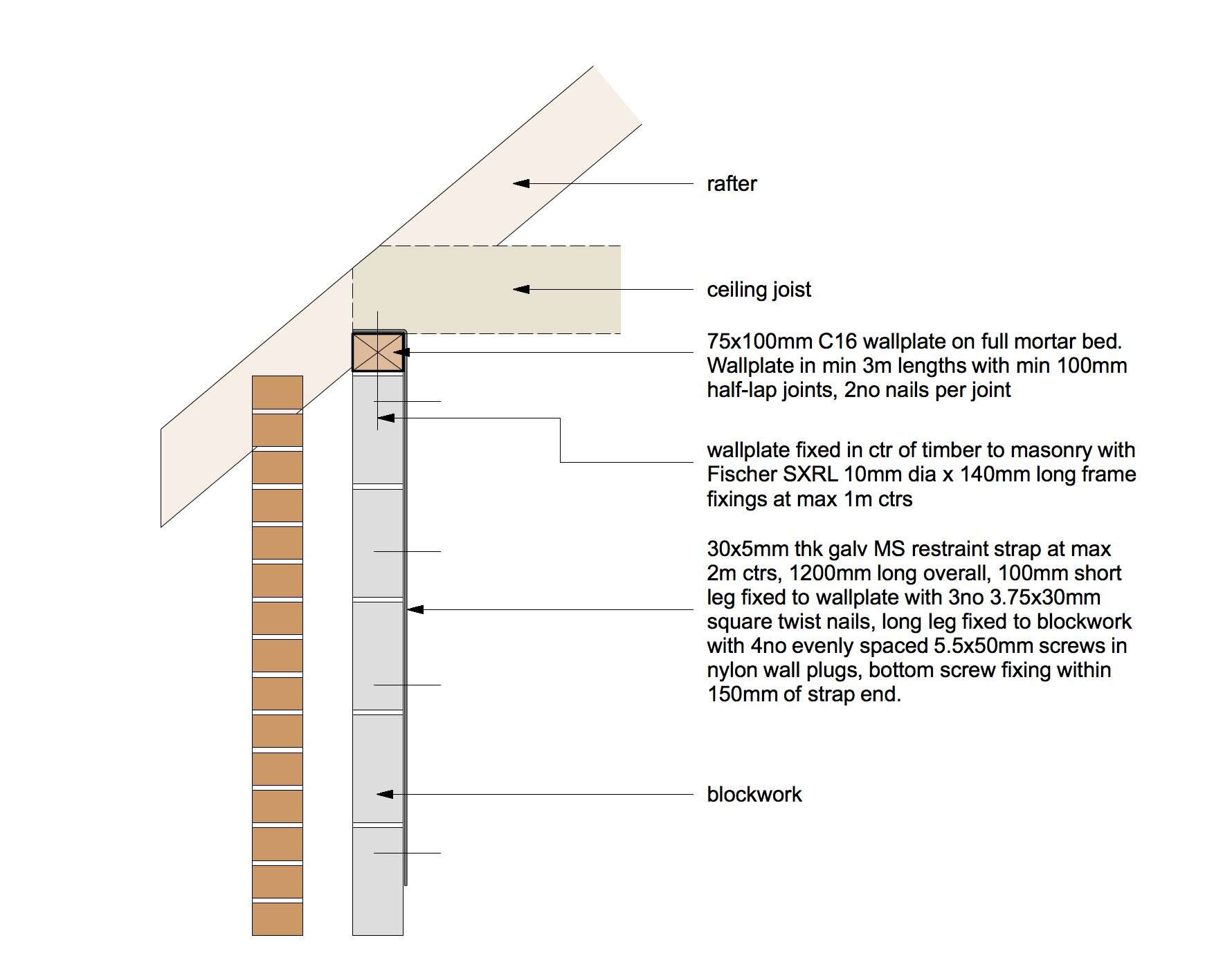
Section through wall plate
Specification:
Wall plate shall be 75x100mm C16 timber lined and levelled and set on full mortar bed and aligned with inner face of external wall. Wall plate shall be in min 3m lengths or, where shorter lengths are necessary, these shall be a single length extending across min 3no rafters. Joints in wall plate (including at wall corners) shall be min 100mm half-lap joints with 2no nail fixings. Wall plate shall be fixed to wall with Fischer SXRL10mm dia frame fixings 140mm long at max 1m ctrs in centre of wall plate, installed after mortar has set. Wall plate shall be strapped with 30x5mm galvanized steel L-shaped restraint straps at max 2m ctrs. Short leg of strap shall be 100mm long and fixed to top of wall plate with min 3no 3.75x30mm square twist nails. Vertical leg of strap shall be min 1m long fixed to inner face of wall with min 4no evenly spaced 5.5x50mm woodscrews in nylon wall plugs, lowest screw to be within 150mm of bottom of restraint strap. All fixings in masonry shall avoid mortar joints and be within middle-third of length/height of masonry unit.
This solution goes further than some of the guidance in certain respects:
the 75x100mm is larger than the guidance requires for the reasons previously outlined.
I have included frame fixings to fix the wall plate to the wall. These also ensure the lateral restraint. The fixing type, size and length need to be compatible with the particular brick or block being used.
I have included a 5mm thick tension strap rather than the 2.5mm thickness advised by some of the guidance documents. This is because there are likely to be requirements for other, similar, restraint straps on the project which will need to be 5mm thickness. It makes practical sense to only have one strap type on the project to avoid the possibility of confusion.
Although the guidance only requires the holding down strap to be included in cases where wind uplift is an issue, I include it as a standard detail in all cases. This is because it's such a simple, inexpensive detail that its not worth omitting it in other cases.
Is the wall plate structural?
The wall plate is more of a constructional device than an element of building structure. The holding down strap, on the other hand, is a structural component which is essential when there is a risk of wind uplift forces overcoming the weight of the roof.
If you are working with a structural engineer, they will probably want to specify the wall plate and strapping details, along with any other restraint details required on the project. This is going to require some co-ordination to ensure that you are both happy with the details and to agree who specifies the detail, as it should either be in your documents or the engineer's, but not both.
I prefer to include the details in the architects information while including a reference in the engineer's specification.
Summary
As you can see, there's plenty of guidance on the subject of wall plates but none of it is comprehensive and some of it is confusing. Obtaining a clear understanding of the issues involved will provide you with confidence when detailing wall plates, and also when inspecting works on site.
There are some lessons from having an in depth look at wall plates which are applicable more generally to other aspects of construction detailing:
Make sure you look at the guidance!
Ask other people how they would do the detail (colleagues, engineers, builders, suppliers, inspectors).
But look at the guidance as well.
If you find something confusing or that you don't fully understand, don't let it go.
Ensure that your documentation is co-ordinated with the engineer's.
Take account of how things happen on site.
If you ask around, you'll probably find that people do things differently so it's worth finding out what guidance they have used and why they do things the way they do. Begin to develop your own views so that you can make your own decisions with confidence.
Your knowledge of building construction will develop from understanding hundreds of small details like this one. It can be difficult to know where to start, so just start somewhere. Your expertise will build over time.
Post Script
I must thank structural engineer Ted Ruffell for adding the following:
Since most rafters are fixed by 'skew nailing', the wall plate needs to have sufficient depth to receive the nails.
In masonry construction, the 'perps' (perpendicular joints) can be more sensitive to load. This is dependent on the nature and strength of the mortar but including the wall plate does help to protect these joints. In that limited sense, the wall plate does act to distribute the load from the rafters.
Add character to your space with beautiful framed art. From modern abstract styles to elegant designs and framed prints, create a statement wall, with a bold wall paint. Or choose framed photo prints and pictures for the living room, highlighted with a wall light.
All Wall Art Canvases Plaques Decorative Accessories
We found no results matching your search.
Set of 2 Floating Botanical Hanging Frames
£25
Set of 2 Abstract Framed Art
£55
Set of 8 Framed Art
£120
World Map Framed Art
£40
Set of 2 Abstract Pictures
£55
The Singing Tree by Fiona Watson Framed Print
£47 - £132
Stretch City Scene Framed Print by Arthouse
£53
Angel Wing Heart Framed Art
£45
Sentiment Hanging Decoration
£4
Honesty Framed Print by Arthouse
£30
Set of 2 Artist Collection Faces by Louise Nisbet Framed Prints
£70
Set of 9 Floating Botanical Framed Art
£65
Brooklyn Plexi Wall Art
£100
Gallery Direct Painted Whirlpool Framed Wall Art
£150
Set of 6 Modern Art Framed Prints
£100
Overlooked Happiness by Fiona Watson Framed Print
£47 - £132
Art For The Home Adilah Tropical Framed Print
£51
Set of 2 Art For The Home Painterly Feathers Wall Art
£75
Set of 3 Dried Botanical Hanging Frames
£40
City Framed Art
£25
Artist Collection 'April Riverside' by Chris Forsey Framed Wall Art
The FA20D engine was a 2.0-litre horizontally-opposed (or 'boxer') four-cylinder petrol engine that was manufactured at Subaru's engine plant in Ota, Gunma. The FA20D engine was introduced in the Subaru BRZ and Toyota ZN6 86; for the latter, Toyota initially referred to it as the 4U-GSE before adopting the FA20 name.
Key features of the FA20D engine included it:
Open deck design (i.e. the space between the cylinder bores at the top of the cylinder block was open);
Aluminium alloy block and cylinder head;
Double overhead camshafts;
Four valves per cylinder with variable inlet and exhaust valve timing;
Direct and port fuel injection systems;
Compression ratio of 12.5:1; and,
7450 rpm redline.
FA20D block
The FA20D engine had an aluminium alloy block with 86.0 mm bores and an 86.0 mm stroke for a capacity of 1998 cc. Within the cylinder bores, the FA20D engine had cast iron liners.
Cylinder head: camshaft and valves
The FA20D engine had an aluminium alloy cylinder head with chain-driven double overhead camshafts. The four valves per cylinder – two intake and two exhaust – were actuated by roller rocker arms which had built-in needle bearings that reduced the friction that occurred between the camshafts and the roller rocker arms (which actuated the valves). The hydraulic lash adjuster – located at the fulcrum of the roller rocker arm – consisted primarily of a plunger, plunger spring, check ball and check ball spring. Through the use of oil pressure and spring force, the lash adjuster maintained a constant zero valve clearance.
Valve timing: D-AVCS
To optimise valve overlap and utilise exhaust pulsation to enhance cylinder filling at high engine speeds, the FA20D engine had variable intake and exhaust valve timing, known as Subaru's 'Dual Active Valve Control System' (D-AVCS).
For the FA20D engine, the intake camshaft had a 60 degree range of adjustment (relative to crankshaft angle), while the exhaust camshaft had a 54 degree range. For the FA20D engine,
Valve overlap ranged from -33 degrees to 89 degrees (a range of 122 degrees);
Intake duration was 255 degrees; and,
Exhaust duration was 252 degrees.
The camshaft timing gear assembly contained advance and retard oil passages, as well as a detent oil passage to make intermediate locking possible. Furthermore, a thin cam timing oil control valve assembly was installed on the front surface side of the timing chain cover to make the variable valve timing mechanism more compact. The cam timing oil control valve assembly operated according to signals from the ECM, controlling the position of the spool valve and supplying engine oil to the advance hydraulic chamber or retard hydraulic chamber of the camshaft timing gear assembly.
To alter cam timing, the spool valve would be activated by the cam timing oil control valve assembly via a signal from the ECM and move to either the right (to advance timing) or the left (to retard timing). Hydraulic pressure in the advance chamber from negative or positive cam torque (for advance or retard, respectively) would apply pressure to the advance/retard hydraulic chamber through the advance/retard check valve. The rotor vane, which was coupled with the camshaft, would then rotate in the advance/retard direction against the rotation of the camshaft timing gear assembly – which was driven by the timing chain – and advance/retard valve timing. Pressed by hydraulic pressure from the oil pump, the detent oil passage would become blocked so that it did not operate.
When the engine was stopped, the spool valve was put into an intermediate locking position on the intake side by spring power, and maximum advance state on the exhaust side, to prepare for the next activation.
Intake and throttle
The intake system for the Toyota ZN6 86 and Subaru Z1 BRZ included a 'sound creator', damper and a thin rubber tube to transmit intake pulsations to the cabin. When the intake pulsations reached the sound creator, the damper resonated at certain frequencies. According to Toyota, this design enhanced the engine induction noise heard in the cabin, producing a 'linear intake sound' in response to throttle application.
In contrast to a conventional throttle which used accelerator pedal effort to determine throttle angle, the FA20D engine had electronic throttle control which used the ECM to calculate the optimal throttle valve angle and a throttle control motor to control the angle. Furthermore, the electronically controlled throttle regulated idle speed, traction control, stability control and cruise control functions.
Port and direct injection
The FA20D engine had:
A direct injection system which included a high-pressure fuel pump, fuel delivery pipe and fuel injector assembly; and,
A port injection system which consisted of a fuel suction tube with pump and gauge assembly, fuel pipe sub-assembly and fuel injector assembly.
Based on inputs from sensors, the ECM controlled the injection volume and timing of each type of fuel injector, according to engine load and engine speed, to optimise the fuel:air mixture for engine conditions. According to Toyota, port and direct injection increased performance across the revolution range compared with a port-only injection engine, increasing power by up to 10 kW and torque by up to 20 Nm.
As per the table below, the injection system had the following operating conditions:
Cold start: the port injectors provided a homogeneous air:fuel mixture in the combustion chamber, though the mixture around the spark plugs was stratified by compression stroke injection from the direct injectors. Furthermore, ignition timing was retarded to raise exhaust gas temperatures so that the catalytic converter could reach operating temperature more quickly;
Low engine speeds: port injection and direct injection for a homogenous air:fuel mixture to stabilise combustion, improve fuel efficiency and reduce emissions;
Medium engine speeds and loads: direct injection only to utilise the cooling effect of the fuel evaporating as it entered the combustion chamber to increase intake air volume and charging efficiency; and,
High engine speeds and loads: port injection and direct injection for high fuel flow volume.
The FA20D engine used a hot-wire, slot-in type air flow meter to measure intake mass – this meter allowed a portion of intake air to flow through the detection area so that the air mass and flow rate could be measured directly. The mass air flow meter also had a built-in intake air temperature sensor.
The FA20D engine had a compression ratio of 12.5:1.
Ignition
The FA20D engine had a direct ignition system whereby an ignition coil with an integrated igniter was used for each cylinder. The spark plug caps, which provided contact to the spark plugs, were integrated with the ignition coil assembly.
The FA20D engine had long-reach, iridium-tipped spark plugs which enabled the thickness of the cylinder head sub-assembly that received the spark plugs to be increased. Furthermore, the water jacket could be extended near the combustion chamber to enhance cooling performance. The triple ground electrode type iridium-tipped spark plugs had 60,000 mile (96,000 km) maintenance intervals.
The FA20D engine had flat type knock control sensors (non-resonant type) attached to the left and right cylinder blocks.
Exhaust and emissions
The FA20D engine had a 4-2-1 exhaust manifold and dual tailpipe outlets. To reduce emissions, the FA20D engine had a returnless fuel system with evaporative emissions control that prevented fuel vapours created in the fuel tank from being released into the atmosphere by catching them in an activated charcoal canister.
Uneven idle and stalling
For the Subaru BRZ and Toyota 86, there have been reports of
varying idle speed;
rough idling;
shuddering; or,
stalling
that were accompanied by
the 'check engine' light illuminating; and,
the ECU issuing fault codes P0016, P0017, P0018 and P0019.
Initially, Subaru and Toyota attributed these symptoms to the VVT-i/AVCS controllers not meeting manufacturing tolerances which caused the ECU to detect an abnormality in the cam actuator duty cycle and restrict the operation of the controller. To fix, Subaru and Toyota developed new software mapping that relaxed the ECU's tolerances and the VVT-i/AVCS controllers were subsequently manufactured to a 'tighter specification'.
There have been cases, however, where the vehicle has stalled when coming to rest and the ECU has issued error codes P0016 or P0017 – these symptoms have been attributed to a faulty cam sprocket which could cause oil pressure loss. As a result, the hydraulically-controlled camshaft could not respond to ECU signals. If this occurred, the cam sprocket needed to be replaced.
The product will be added to Cart Space Solutions 18" Metal 2 Drawer Mobile Smart Vertical File Cabinet Black
Plan Includes
Protection Plan
MFR Warranty
Accidental stains & damage
30-day risk-free refund
Full repair with no deductible
Immediate coverage
24/7 claim filing
Learn More
Back
Protection Plan Details
Enjoy the comfort of premium coverage with a Uniters Protection Plan
Plan Includes
Protection Plan
MFR Warranty
Accidental stains & damage
30-day risk-free refund
Full repair with no deductible
Immediate coverage
24/7 claim filing
Frequently Asked Questions
What does this Protection Plan cover?
This plan covers all accidental stains as well as accidental damage to your furniture.
What's covered under "accidental damage?
In terms of accidental damage, this plan covers all unintentional stains, rips, tears, burns, punctures, gouges, chips, dents, and water rings.
Once I've purchased a plan, when does my coverage begin?
Coverage for accidental damage begins the day your product is delivered.
What isn't covered by this plan?
This plan does not cover damages caused by accumulation, neglect, abuse, or failure to comply with the manufacturer's warranty. It also does not cover damages caused by natural disasters such as a fire or flooding, or furniture used in commercial settings.
What isn't covered by this plan?
See full list of exclusions.
How do I submit a claim?
You can submit a claim to Uniters on their website or app, or give them a call at the phone number listed on your Protection Plan certificate.
Will I have to pay a deductible?
Nope!
Can I cancel my plan?
You can cancel your plan for a full refund within 30 days of purchase. After 30 days, your refund will be prorated. Any previous claims or an administrative fee may be deducted from your refund.
See Plan Terms & Conditions
We've partnered with Uniters* to provide you with best-in-class Protection Plan options. Should your furniture, area rug, or mattress need cleaning or repairs, you can rest easy—they've got you covered.
If you purchase this Plan in the following states, AL, AK, CA, CO, CT, DE, DC, GA, IA, ID, IL, IN, KS, KY, LA, MD, MA, ME, MI, MN, MO, MS, MT, NE, ND, NH, NJ, NV, NY, OH, OR, PA, RI, SC, SD, TN, TX, UT, VT, WI, WV, the Provider of this Plan and the entity responsible for fulfilling the terms of this Plan is Tarmo, LLC, 777 South Flagler Drive, West Palm Beach, Florida, 33401, receiving mail at P.O. Box 11355, West Palm Beach, Florida 33419. We reserve the right to transfer our obligations to another entity. If you purchased this Plan in Florida, the Provider of this Plan and the entity responsible for fulfilling the terms of this Plan is Dealers Assurance Company (License # 02977), receiving mail at 240 N. Fifth Street, Suite 350, Columbus, OH 43215.If you purchased this Plan in AZ, NC, NM, OK, VA, or WA, the Provider of this Plan and the entity responsible for fulfilling the terms of this Plan is Dealers Alliance Corporation, 240 N. Fifth Street, Suite 350, Columbus, OH 43215.
Chandrayaan-2 mission is a highly complex mission, which represents a significant technological leap compared to the previous missions of ISRO, which brought together an Orbiter, Lander and Rover with the goal of exploring south pole of the Moon. This is a unique mission which aims at studying not just one area of the Moon but all the areas combining the exosphere, the surface as well as the sub-surface of the moon in a single mission.
Why did we go to the Moon?
The Moon is the closest cosmic body at which space discovery can be attempted and documented. It is also a promising test bed to demonstrate technologies required for deep-space missions. Chandrayaan-2 aims for enhancing our understanding of the Moon, stimulate the advancement of technology, promote global alliances and inspire a future generation of explorers and scientists.
What are the scientific objectives of Chandrayaan 2 ? Why was the Lunar South Pole targetted for exploration?
Moon provides the best linkage to Earth's early history. It offers an undisturbed historical record of the inner Solar system environment. Though there are a few mature models, further explanations were needed to understand the origin of the Moon. Extensive mapping of lunar surface to study variations in lunar surface were essential to trace back the origin and evolution of the Moon. Evidence for water molecules discovered by Chandrayaan-1, required further studies on the extent of water molecule distribution on the surface, below the surface and in the tenous lunar exosphere to address the origin of water on Moon.
The Lunar South pole is especially interesting because of the lunar surface area that remains in shadow is much larger than that at the North Pole. There could be a possibility of presence of water in permanently shadowed areas around it. In addition, South Pole region has craters that are cold traps and contain a fossil record of the early Solar System.
Launcher and the Spacecraft
Launcher
The GSLV Mk-III is India's most powerful launcher to date, and has been completely designed and fabricated from within the country.
Click here >
Orbiter
The Orbiter will observe the lunar surface and relay communication between Earth and Chandrayaan 2's Lander — Vikram.
Click here >
Vikram Lander
The lander was designed to execute India's first soft landing on the lunar surface.
Click here >
Pragyan Rover
The rover was a 6-wheeled, AI-powered vehicle named Pragyan, which translates to 'wisdom' in Sanskrit.
Click here >
Timeline of the mission
18th September, 2008
Prime Minister Manmohan Singh approves the Chandrayaan2 lunar mission
Showrooms feature stock, semi-stock, or custom kitchen cabinets.
Photo: Ben Herzog Architect, PC
In-Stock and Semi-Stock Kitchen Cabinet Options Ready-to-assemble open-frame and pre-assembled kitchen cabinets are easy and convenient to purchase and install. Available in-stock at most large home centers, these no-frill cabinets typically feature engineered wood construction with a melamine finish and steel-sided drawers. Style and finish choices are limited, but it is the most economical way to go. In-stock cabinets cost less to purchase, but professional installation is still an option.
Semi-stock cabinets let the homeowner create a more personalized space, but often require four to six weeks for delivery. Home centers offer showroom displays of semi-custom cabinets while staff designers help customers visualize their kitchen space and design a plan to meet their needs.
Semi-custom cabinets feature higher quality workmanship and materials than in-stock units, and offer a greater selection of design features like plate racks, corner cupboards, sliding shelves, or pantries. Styles and finishes vary widely, but semi-stock cabinets typically have sides constructed of engineered wood or plywood and solid wood doors or faces.
Oak, maple, cherry, and hickory are all popular woods for kitchen cabinets. Veneers over plywood are another option. Cabinets may be open or framed, but drawers are usually constructed from solid wood and are dovetail or dowel assembled.
In-stock and semi-stock cabinets are built to industry specs. Standard base cabinets built in the U.S. are 34-1/2 inches high and 24 inches deep. Cabinet sides are typically 3/4 of an inch. Wall cabinets, except those above a range hood or refrigerator, are 30 inches high and 12 inches deep. Some manufacturers will customize a semi-stock cabinet by giving the buyer the ability to decrease the depth of a base or wall cabinet. Widths increase in three-inch increments from six to 48 inches. Trim work or filler is used to make up the difference when cabinet measurements do not fit the space exactly.
Custom Kitchen Cabinets When it comes to custom cabinetry, your budget is the only limit. A custom-built cabinet is not constructed until it is ordered. Most people assume that custom work will be the most expensive option, this is not always the case. Upper-end semi-stock cabinets often cost the same as basic custom cabinetry. For example, if the only issue is cabinet width, a custom unit can be built to the homeowner's specs using engineered wood, which costs far less than solid wood but still allows for a custom fit.
If expense is not an issue, custom-built kitchen cabinets provide the best of all worlds to the homeowner with discriminating taste. Choices include hand-selected wood, reclaimed wood, and exotic woods like mahogany. Cabinetmakers will even match the paint or finish of an existing hutch or corner cupboard. Homeowners can select everything from glass doors with the look of authentic hand-blown glass to inset doors with decorative beading. Pie-cut corner cabinets, full extension glides on drawers, and Super-Susans provide added convenience.
Custom cabinetmakers vary in their delivery time. Depending on the complexity of the job, a homeowner should allow six to 12 weeks for construction and delivery. Installation takes time, too. Some jobs require up to six months and much on-site time.
 Overhead brace floor mounted partitions are the most common in the United States. This style is an easy installation with no ceiling or special flooring needed. The most economical solution for high traffic areas and overall height is 82".
 Ceiling hung partitions are great for easy floor maintenance with a clean and contemporary appearance. Maximum ceiling height is 123.5" with most manufactures.
 Floor mounted partitions are great for lower ceilings and lower traffic areas. The overall height is 70".
 Floor to ceiling braced partitions are the best for high traffic areas such as airports and high schools. Extra support from floor to ceiling. Maximum ceiling height is 122" with most manufactures.